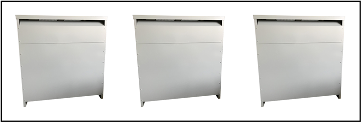
Current Limiting Reactor, 3000 Continuous Amps, 480 VAC L-L,
40000 Available Amps, 7500 Fault Limit Amps, P/N KK-29
A current-limiting reactor is used when the prospective short-circuit current in a distribution or transmission system is calculated to exceed the interrupting rating of the associated switchgear. The inductive reactance is chosen to be low enough for an acceptable voltage drop during normal operation, but high enough to restrict a short circuit to the rating of the switchgear. The amount of protection that a current-limiting reactor offers depends upon the percentage increase in impedance that it provides for the system.
The main motive for using current-limiting reactors is to reduce short-circuit currents so that circuit breakers with lower short-circuit breaking capacity can be used. They can also be used to protect other system components from high current levels and to limit the inrush current when starting a large motor.
The customer application is shown below:

Current Limiting Reactor, Three Phase
The inductance calculations are shown below:
- L-L = 480 VAC
- V L-N = 277 VAC
- Available Fault Current = 40000 Amps
- Fault Current = 7500 Amps
- Z system (based on Available Current) = 277 / 40000 = 0.006925 Ohms
- Z system (based on Designed Fault Current) = 277 / 7500 = 0.03693 Ohms
- Z needed = Square Root of (0.03693² – 0.006925²) = 0.036 Ohms
- Inductance = 0.036 / (2 x 3.142 x 60) = 96.3 uH
- Reactance Voltage Drop = 0.036 Ohms x 3000 Amps = 108 VAC
- Percentage Voltage drop = 108 / 277 = 39 %
Specifications:
A. CLR, 3000 Amps continuous, 3 PH, 60 Hz, 480 V, P/N KK-29
B. Available fault current: 40000 Amps
C. Fault current: 7500 Amps
D. Copper windings
E. Approvals: none
F. System shipping weight: 1500 lbs. or TBD
G. Three inductors in three separate indoor enclosures (125″W x 100″H x 125″D)
H. Calculated Inductance Value: 96.3 uH, 3000 Amps continuous
I. Percentage Voltage Drop: 39 %
The detail of one Air Core Inductor, KK-29-1 is shown below. Three KK-29-1 are required for one CLR KK-29.

KK-29-1. Three are required per system
Specifications:
- Air Core Inductor, P/N KK-29-1
- L (1, 2) = 96.3 uH
- Continuous Current: 3000 Amps
- Frequency: 60 Hz
- Copper windings
- Approvals: None
- Copper bus bars are 6″ x 1/4″ thick
- One CLR consists of three separate air core inductors in three indoor enclosures
The System consists of three inductors in three separate indoor enclosures. Indoor Enclosure Dimensions are 125″W x 100″H x 125″D

Three Inductors in three separate indoor enclosures
All our CLR’s are custom-built to order. To discuss your specific application, please call our phone number at (714) 624-4740, or send us an email at quote@lcmagnetics.com.
